Seabird CTD-Carousel Setup & Deck Unit Diagnostics
 |
 |
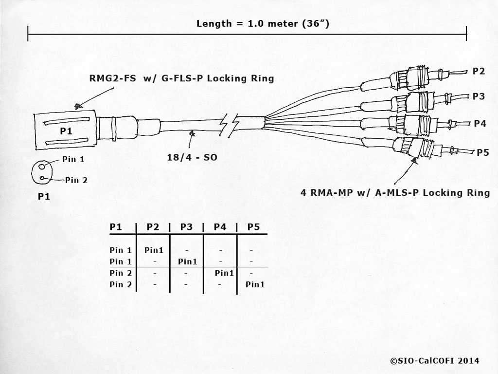
SIO-CalCOFI’s method of terminating the sea cable uses a custom 4-pin pigtail to terminate a multi-strand conductive wire that allows each individual conductor to be used in any combination. Terminating the sea cable using this technique may be viewed in the CalCOFI Handbook: CTD Termination.
Conventional two-pin Seabird pigtail terminations are standard on NOAA vessels and are usually performed by the ET. So interfacing the CTD deck unit only requires the attachment of the sea cable to the deck unit. This is done by connecting a two-conductor wire, such as Seabird part no. 31371 or a coaxial cable equipped with MS3106A connector, from the winch junction box in the CTD lab to the Sea Cable port on the back of the deck unit (see the deck unit section below).
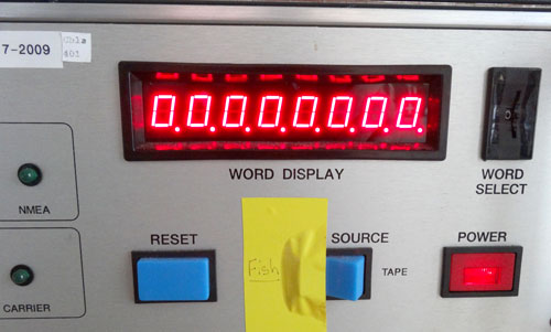
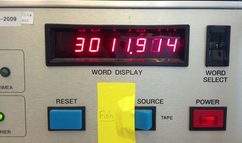
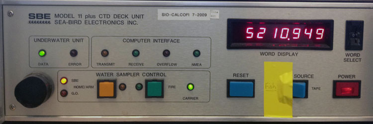
Once the sea cable is connected to the Seabird 9plus and Seabird 11plus deck unit, the deck unit can be powered on. If cabled properly and all electronics are functioning, the numeric LED panel of the deck unit should display non-zero numbers. These values are different for each channel which can be selected by rotating the WORD SELECT dial to the right of the LED panel.
If the LED panel displays “0.0.0.0.0.0.0.0” then the deck unit and CTD “fish” are not handshaking correctly. Turn the deck unit off and wait 60 seconds before touching any exposed wire. Typically, with only two pins, the problem is reversed polarity so switching the wires in the junction box will correct this issue. Please note that powering on the deck unit with reversed polarity may blow the fuse(s). So after switching the wires and before re-powering on the deck unit, check both the 1/2A and 2A fuses on the back of the deck unit & replace if necessary. It is prudent to keep a good supply of these fuses on hand. Power on the deck unit and hopefully, the LED panel has numbers.
Please note in the photos, yellow tape is used to keep the deck unit Signal Source set to Fish. If the switch is toggled to Tape, the deck unit will not communicate with the CTD. The yellow tape prevents the switch from changing from Fish to Tape unintentionally.
Deck Unit to PC Setup
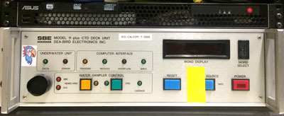 |
| Seabird SBE11 v2 Deck Unit Front |
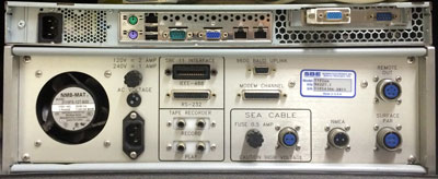 |
| Seabird SBE11 v2 Deck Unit Back |
SIO-CalCOFI interfaces our Seabird SBE9plus CTD to a data acquisition computer using a SBE 11plus v2 deck unit. The data acquistion computer (ASUS blade PC) runs Seasave v7.x under Windows 7 64bit for real-time display of CTD sensor profiles vs depth. Our PC has one (functioning) 9-pin com port so a usb-to-serial adapter is used as the second com port. The primary com port (com 1) is used for data acquisition and usb-serial virtual com port (com 2) connects to the SBE32 carousel via modem channel. If inputs such as GPS or outputs such as Remote Depth Readout require serial ports, additional com ports are required. We use additional usb to serial adapters when necessary and configure the com port settings in Seasave.
Cable connections:
- PC 9-pin com 1 attaches to deck unit 25-pin RS-232 port using a 9F-25M pin serial cable.
- PC usb-serial com 2 attaches to deck unit 25-pin Modem Channel using a FTDI usb-serial adapter with 9F-25M pin serial cable.
- Deck unit Sea Cable connection attaches the CTD termination, using a two-wire coxial cable with 2-pin MS-style male connector (MS3106A-12S-3P, SBE PN 50086), to the ship's CTD winch wire junction box.
- Deck unit NMEA port connects to the ship's GPS serial feed using the ship's 2-pin MS type female connector to GPS feed or Seabird 801424 NMEA interface cable to GPS serial feed. On some vessels, such as RV Reuben Lasker, the NMEA GPS may interface with the PC com port so an additional serial connection is necessary (CalCOFI 1701RL, for example).
- Deck unit SURFACE PAR connects to the SIO-CalCOFI or ship's reference PAR using a 4-pin MS-style male connector custom cable.
- Deck unit REMOTE OUT connects to the SBE14 Remote Depth Readout Box using the 100m Seabird cable - this is installed by SIO-CalCOFI in the CTD winch house. On some vessels, such as RV Reuben Lasker, the Remote Depth Readout box may already be installed and interface via serial port. So another com port or usb to serial connection is necessary (CalCOFI 1701RL, for example).
Once all connections are made, the deck unit is powered on. If the CTD & deck unit 'handshake' properly and data are being received by the deck unit. The front LED panel should display non-zero numbers that change when displaying the frequency channels. The led indicator lights on the front of the deck unit are also useful diagnostic indicators. If NMEA GPS is connected to the deck unit and is being received properly, the 'COMPUTER INTERFACE' NMEA led will light green (note: GPS connected to the PC instead of the deck unit will not illuminate the deck unit NMEA led). If CTD data are being received by the deck unit, the 'UNDERWATER UNIT' DATA led will light green. If data are being received by the PC, the 'COMPUTER INTERFACE' RECEIVE led will light green. If either the ERROR led or OVERFLOW led light up & stay lit there is a problem. They will flash during the handshaking startup and this is normal. Refer to the Seabird manual for troubleshooting advice. Typically the OVERFLOW led indicates a problem between the deck unit and pc, usually with Seasave data acquisition. The ERROR led indicates a problem with the deck unit communicating with the CTD, perhaps a termination problem.
Seasave Setup
Once the deck unit and CTD ('fish') are ‘talking’, it is time to interface the deck unit and data acquisition computer. Seasave v7 requires Microsoft Windows and a minimum of two serial ports if using a SBE carousel. On computers that do not have serial ports, an usb to serial adapter is necessary. Please note Windows 8 or 10 have not been tested by CalCOFI to run Seasave - we use Windows 7.
Instrument Configuration:
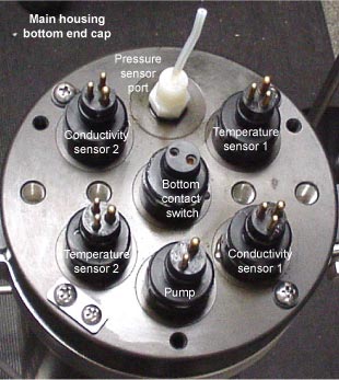
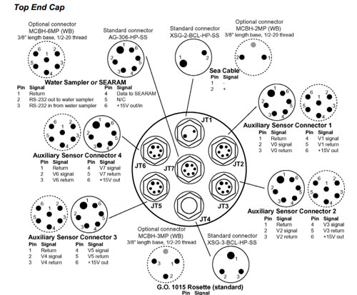
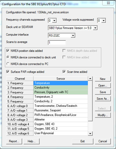
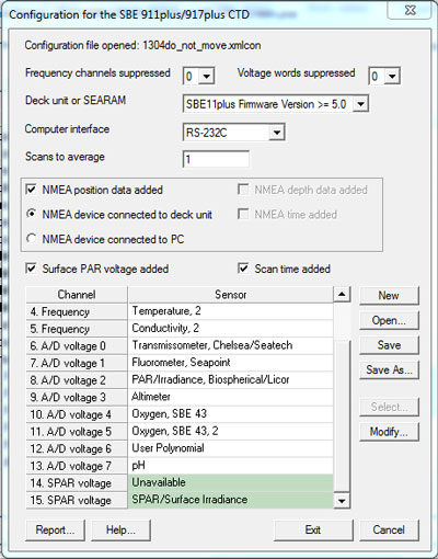
Proper setup of the sensor configuration on the fish is the most critical aspect of Seasave setup. Not only do you have to configure the proper sensor to each channel but recording the serial numbers is required for proper entry of calibration coefficients. It is important during the connecting of sensor cables to the fish to write down the CTD channel (see fig), sensor type & serial number. This sensor ‘map’ is used to configure the instrument in Seasave. Seabird provides a disc with specific calibration files for each sensor so the importing of coefficients may be done without key-entering numbers. This will eliminate common key-entry transcription errors.
 |
|
 |
|
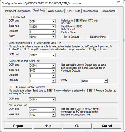
Serial Ports:
Once the instrument configuration has been completed, move to the next tab in Seasave – Serial Ports. Data acquisition is typically configured on com 1 (or the first serial com port available) using the default com settings (see fig). The water sampler modem channel is configured on com 2 (or the 2nd com port available). GPS may be configured on a third serial port, if available, or attached directly to the deck unit NMEA port, with a MS3106A connector. Remote Depth Readout may also require a com port and proper settings.
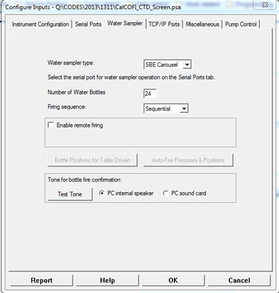
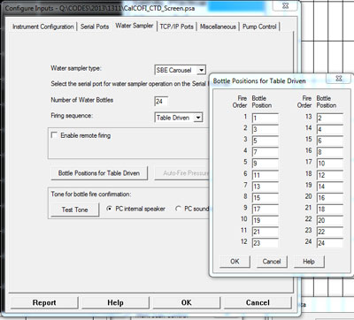
Water Sampler:
The SBE Carousel water sampler is typically setup for sequential firing (see fig). The sampler may also be programmed, table-driven, where the fire order is programmed. This is often used by SIO-CalCOFI when only 12 bottles are fired on a 24-bottle system, creating a balanced load for recovery.
|
|
|
|
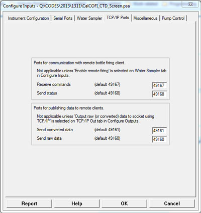
TCP/IP Ports: These are not typically changed or used so no changes are recommended. |
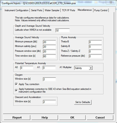
Miscellaneous:
Default settings are typically fine (see fig). Entry of the working area median latitude may be entered so depth & sound velocity can be correctly calculated when GPS is not available. |
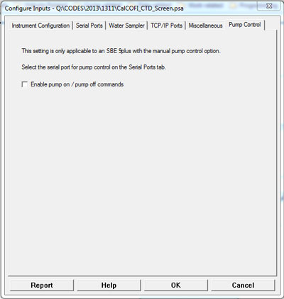
Pump Control: The pumps automatically turn on when the conductivity sensor detects seawater. So this setting is only applicable to SBE 9+ with a manual control option. |
|
|
|
|
Starting Data Acquisition
Now that the deck unit is successfully talking to the fish (LED deck unit panel is displaying numbers) and the instrument has been configured, it is time to start data acquisition. Power on the deck unit and monitor the LED panel and lights, they will go through a startup series of flashes and LED number rotations. After several seconds, the LED panel value should stabilize. If the GPS is attached to the deck unit and communicating properly, the NMEA light will be lit green.
 |
|
|
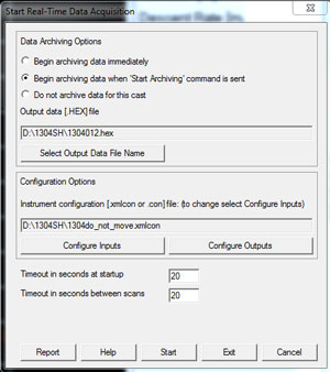
In Seasave, select Real-Time Data from the menu then Start. Select an output data file name then verify the configuration is the one created when the sensors were mapped and coefficients entered. Click the Start button to begin data communications, typically data are not archived immediately. The system will go through a series of handshaking, checking communications with the deck unit, the carousel, and GPS. If everything is talking, real-time data should display on screen. Verifying the sensor pairs agree is important for determining the coefficients and sensor channels are correct. Check the numbers, particularly the temperature since salinity will be ~0 and oxygen unstable out of water. But verify the salinity and oxygen sensor values are between 0 – 7, and not some impossible values. Verify other sensor measurements are responsive – for PAR, cap & uncap the sensor, monitoring values changes; fluorometer, place a chlorophyll standard (or fingertip, which will fluoresce; do not touch the optical surface) in the optical path; transmissometer, unblocked & blocked; then address any misconfiguration issues.
|
|
|
|
|
Only four parameters can be displayed on a single X-Y plots. Recent versions of Seasave allow the changing of axes ranges without losing the profile traces. So profiles that go offscale or need a lower range can be adjusted during the cast. CalCOFI displays T, S, O2, & Fluorometer on its main cast plot (black background in the photo). Two fixed data displays are setup up: one for easy recording of the console ops form values; one for all sensor data for deck verification. The all-sensor fixed display sits mid-screen and is monitored closely for snesor agreement between the primary & secondary pairs (T1-T2, S1-S2, O21-O22). LTER sampling depths are determined by the chlorophyll profile so there is a 0-150m plot (under the cast plot) that is displayed during the down cast for better profile viewing. |

Testing the Water Sampler
Once you are sure the all systems are communicating, it is time to test the water sampler. This typically requires two people on two radios. Once person sits at the CTD console and manually fires each bottle position; one stands over the carousel and puts tension on each sequential release trigger. It takes the deck unit a few seconds to recharge the capacitor so wait 5secs minimum between button presses/bottle fires. This should NOT be done with open spring-loaded bottles since closing them in air can crack the bottle. All 24 positions should be triggered and confirmed - if any trigger sticks, service or replace it.
Transmissometer Calibration
If a transmissometer is mounted on the system, a deck calibration is usually done to calculate the M & B coefficients (see Seabird Application Note #7: webpage or PDF).
This is performed by cleaning the optics of the transmissometer (SIO-CalCOFI uses a mild soap squirt bottle to rinse the two optical lenses without abrading the optical surfaces), recording the maximum voltage, then blocking one end and recording the minimum value. These values combined with the factory coefficients are used to calculate M & B – these coefficients are entered into the Seabird transmissometer sensor configuration. This calibration allows transmissometer beam attenuation coefficient & % light transmission measurements recorded by the CTD to be accurate.
This typically concludes the CTD setup and the system is ready for its first deployment. Please refer to the CTD General Practices document for additional instructions.
Document prepared by JRW 12Sep2013, latest update 01Feb2017